


MS Value-Oriented Pump
Modeled after the classic S-type pump, MS series offers ideal value for money for budget-oriented customers.
| Outlet diameter | 100~1200mm |
| Flow capacity | 70~14000 m3/h |
| Head | 8~150 m |
| Operating temperature | -20~200°C |
| Working pressure | Up to 4MPa |
MS type pump is S series of the renewal of energy-efficient products, widely used in modern urban water supply and sewerage, power generation, industrial process water intake, compression, irrigation systems and hydraulic engineering, petrochemical engineering and so on.
MS type pump adopts national standard specification for design, its serialization, standardization, high degree of generalization, superior performance, stable operation, safe and reliable. New structures be used in the design, easy to maintain, repair and maintenance; introducing new material may be applicable multiple media to delivery.
Main performance parameters
Pump outlet diameter Capacity Head Temperature Solid parameter Permissible pressure |
Dn:100~1200mm Q: 70~22392m3/h H: 8~150m T: -20℃~200℃ ≤80mg/L ≤4Mpa
|
Description of Pump Type
For example:500MS35A-L-M(F、Y)-J
500 The diameter of the inlet (mm)
MS Single stage double suction, centrifugal split case pump
35 Head(m)
A-Changed outer diameter of impeller (the max diameter without mark)
L-Vertical type
M-Anti-frication
F-Anti-corrosion
Y-Anti-oil
J-Pump speed changed(Maintain the speed without mark)
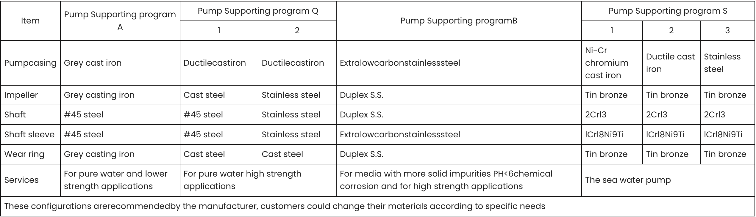
Pump Supporting program
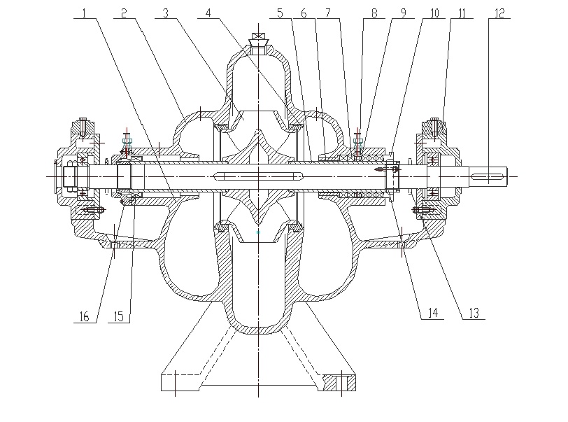
Construction drawing I
 |  |
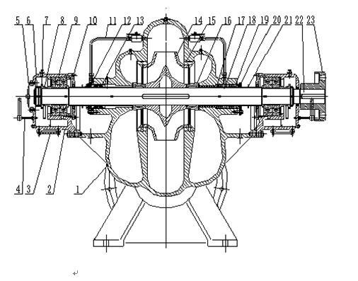
Construction drawing II
 | 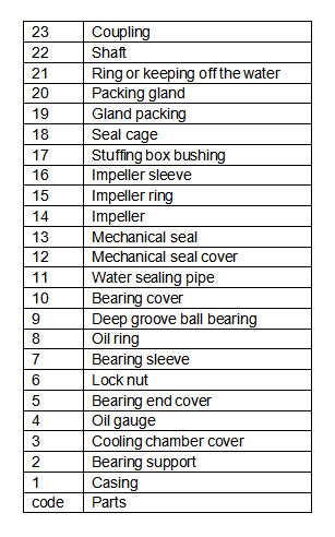 |
1. Structure of casing: Open structure in axial, inlet and outlet of the pump both on the pump body, and in the same plane perpendicular to the axis. Easy to lay pipes and repair (when repairing, open the pump cover and rotor parts without removing inlet and outlet of pipes and motor).
2. Structure of rotor: Adopt double-suction impeller, using its symmetric arrangement of leaves to balance the effect of the radial force. Impeller fixed on the shaft relying on either side of the shaft sleeve and sleeve nut, align axial position accurately by adjusting the sleeve nut. Both ends of the shaft support structure connect motor directly through elastic pin coupling, effectively reducing mechanical losses; deep groove ball bearings and grease lubrication insure smooth operation.
3. Vortex structure: Pump body, pump cover and impeller constitute the suction Chamber and water pressure Chamber. Install a seal ring between the suction chamber and water pressure chamber to reduce water leakage from water pressure Chamber back to the suction Chamber, which reduces the capacity of losses, while effective protect the pump body, extending the life of pump case. On in and out of the flange, reserved the installation of spiral hole for vacuum and pressure gauges; on lower portion of in and out of the flange, reserved spiral hole of drainage for easy Automation Control System access.
4. Structure of shaft seal: There are packing seals and mechanical seals, may also adopt soft packing seals according to special requirements. Depending on the media properties water seal water (washing water) can use water of pressure chamber or external supply water.

|
Type |
Capacity |
Head |
Speed |
Shaft power |
Motor power |
EFF |
NPSH |
The structural form |
||
|
(m³/h) |
(l/s) |
(m) |
(r/min) |
(kw) |
(kw) |
(%) |
(m) |
|||
|
150MS50 |
|
130 160 220 |
36.1 44.4 61.1 |
52 50 40 |
2980 |
25.3 27.3 31.1 |
37 |
72.9 80 77.2 |
3.9 |
Structure drawing I |
|
A |
112 144 180 |
31.1 40 50 |
43.8 40 35 |
2980 |
18.5 20.9 24.5 |
30 |
72 75 70 |
3.9 |
||
|
B |
103 133 160 |
28.6 36.9 44.4 |
38 36 32 |
2980 |
17.2 18.6 19.4 |
22 |
65 70 72 |
3.9 |
||
|
150MS78 |
|
126 160 198 |
35 44.4 55 |
84 78 70 |
2980 |
40 45 51 |
55 |
72 75 74 |
5.9 |
|
|
A |
112 144 180 |
31.1 40 50 |
67 62 55 |
2980 |
30 33.8 33.5 |
45 |
68 72 70 |
5.9 |
||
|
150MS97 |
|
126 180 216 |
35 50 60 |
104 97 87 |
2980 |
49 59 64 |
75 |
73 80 79 |
3.8 |
|
|
A |
119 170 204 |
33 47.2 56.6 |
91 85 76 |
2980 |
42 50 55 |
75 |
70 78 77 |
3.7 |
||
|
J |
72 90 108 |
20 25 30 |
24 22.5 20 |
1480 |
6.5 7.5 8.5 |
11 |
73 74 70 |
2.7 |
||
|
200MS42 |
|
216 280 342 |
60 77.7 95 |
48 42 35 |
2980 |
34.8 38.1 40.2 |
55 |
81 84.2 81 |
5.4 |
|
|
A |
198 270 310 |
55 75 86.1 |
43 36 31 |
2980 |
30.5 33.1 34.4 |
37 |
76 80 76 |
5.4 |
||
|
200MS63 |
|
216 280 351 |
60 77.7 97.5 |
69 63 50 |
2980 |
54.8 58.3 66.4 |
75 |
74 82.7 72 |
5.4 |
|
|
A |
180 270 324 |
50 75 90 |
54.5 46 37.5 |
2980 |
41.1 45.1 47.3 |
55 |
70 75 70 |
5.4 |
||
|
200MS95 |
|
183 280 324 |
50.8 77.7 90 |
103 95 85 |
2980 |
83.1 91.7 100 |
110 |
62 79.2 75 |
4.7 |
|
|
A |
198 270 310 |
55 75 86.1 |
94 87 80 |
2980 |
74.5 85.5 91.1 |
110 |
68 75 74 |
4.5 |
||
|
250MS14 |
|
360 485 576 |
100 134.7 160 |
17.5 14 11 |
1480 |
21.4 21.5 22.1 |
30 |
80 85.8 78 |
3.2 |
|
|
A |
320 430 504 |
88.8 119.4 140 |
13.7 11 8.6 |
1480 |
15.4 15.8 15.8 |
22 |
78 82 75 |
3.2 |
||
|
250MS24 |
|
360 485 576 |
100 134.7 160 |
27 24 19 |
1480 |
33.1 36.9 36.4 |
55 |
80 85.8 82 |
3.5 |
|
|
A |
342 414 482 |
95 115 133.8 |
22.2 20.3 17.4 |
1480 |
25.8 27.6 28.6 |
30 |
80 83 80 |
3.5 |
||
|
Type |
Capacity |
Head |
Speed |
Shaft power |
Motor power |
EFF |
NPSH |
The structural form |
||
|
(m³/h) |
(l/s) |
(m) |
(r/min) |
(kw) |
(kw) |
(%) |
(m) |
|||
|
250MS39 |
|
360 485 612 |
100 134.7 170 |
42.5 39 32.9 |
1480 |
54.8 61.5 68.6 |
75 |
76 84 79 |
3.2 |
Structure drawing I |
|
A |
324 468 576 |
90 130 160 |
35.5 30.5 25 |
1480 |
42.5 49.3 50.9 |
55 |
74 79 77 |
3.2 |
||
|
250MS65 |
|
360 485 612 |
100 134.7 170 |
71 65 56 |
1480 |
92.8 109 129.6 |
132 |
75 79 72 |
6.7 |
|
|
A |
338 462 535 |
93.8 128.3 148.6 |
60 53 49 |
1480 |
73.6 84.4 95.2 |
110 |
74 77 75 |
6.7 |
||
|
250MS110 |
|
400 545 600 |
111.1 151.3 166.6 |
115 110 102.4 |
1480 |
169 206.6 217 |
250 |
74 79 77 |
2.3 |
|
|
300MS12 |
|
612 790 900 |
170 219.4 250 |
14.5 11.25 10 |
1480 |
30.2 31.1 33.1 |
37 |
80 85 74 |
5.8 |
|
|
A |
515 675 781 |
143 187.5 216.9 |
11.5 9.7 8.5 |
1470 |
22.1 22.9 23.8 |
30 |
72 78 76 |
5.8 |
||
|
300MS19 |
|
612 790 935 |
170 219.4 259.7 |
22 19 14 |
1480 |
45.9 47 47.6 |
55 |
80 87 75 |
5.8 |
|
|
A |
485 693 798 |
134.7 192.5 221.6 |
18.5 14.8 12.1 |
1480 |
34.4 34.9 35.1 |
45 |
71 80 75 |
5.8 |
||
|
300MS32 |
|
612 790 960 |
170 219.4 266.6 |
38 32 29 |
1480 |
76.2 79.2 95 |
110 |
83 87 80 |
5.8 |
|
|
A |
537 702 720 |
149.1 195 200 |
29.5 24.7 22.8 |
1480 |
53.9 56.2 62.9 |
75 |
80 84 78 |
5.8 |
||
|
300MS58 |
|
576 790 972 |
160 219.4 270 |
65 58 50 |
1480 |
136 148.5 165.5 |
185 |
75 84 80 |
5.8 |
|
|
A |
529 720 893 |
146.9 200 248 |
55 49 42 |
1480 |
99.2 118.6 131 |
160 |
79 81 78 |
5.8 |
||
|
B |
504 684 835 |
140 190 231.9 |
47.2 43 37 |
1480 |
88.8 100 108 |
132 |
73 90 78 |
5.8 |
||
|
300MS90 |
|
590 790 936 |
163.8 219.4 260 |
93 90 82 |
1480 |
202 242 279 |
315 |
74 80 75 |
5.8 |
|
|
A |
576 756 918 |
160 210 255 |
86 78 70 |
1480 |
190 217 247 |
280 |
71 74 71 |
5.8 |
||
|
B |
540 720 900 |
150 200 250 |
72 67 57 |
1480 |
151 180 200 |
220 |
70 73 70 |
5.8 |
||
|
Type |
Capacity |
Head |
Speed |
Shaft power |
Motor power |
EFF |
NPSH |
The structural form |
||
|
(m³/h) |
(l/s) |
(m) |
(r/min) |
(kw) |
(kw) |
(%) |
(m) |
|||
|
350MS16 |
|
972 1260 1440 |
270 350 400 |
20 16 13.4 |
1480 |
64 64.5 71 |
75 |
83 86 74 |
5.3 |
Structure drawing I |
|
A |
800 967 1167 |
222.2 268.6 324.1 |
13.7 11.5 8.6 |
1480 |
40.3 38.8 39 |
55 |
74 78 70 |
5.3 |
||
|
350MS26 |
|
972 1260 1440 |
270 350 400 |
32 26 22 |
1480 |
99.7 101.5 105 |
132 |
85 88 82 |
5.3 |
|
|
A |
843 1088 1264 |
234.1 302.2 351.1 |
24.7 20.4 15.7 |
1480 |
70.9 72.8 74 |
90 |
80 83 73 |
5.3 |
||
|
350MS44 |
|
972 1260 1476 |
270 350 410 |
50 44 37 |
1480 |
164 177.6 189 |
220 |
81 87 79 |
5.3 |
|
|
A |
876 1260 1476 |
243.3 350 410 |
42 37 31 |
1480 |
125.2 151.1 155.8 |
200 |
80 84 80 |
5.3 |
||
|
350MS75 |
|
972 1260 1440 |
270 350 400 |
80 75 65 |
1480 |
271 304 349 |
355 |
78 85 80 |
5.3 |
|
|
A |
900 1170 1332 |
250 325 370 |
70 65 56 |
1480 |
220 247 257 |
280 |
78 84 79 |
5.3 |
||
|
B |
813 1060 1202 |
225.8 294.4 333.8 |
57 53 45.8 |
1480 |
168 187 195 |
220 |
75 82 77 |
5.3 |
||
|
350MS125 |
|
850 1260 1660 |
236.1 350 461.1 |
140 125 100 |
1480 |
462 531 623 |
710 |
70 81 72.5 |
5.3 |
|
|
A |
787 1157 1538 |
218.6 321.3 427.2 |
120 107 86 |
1480 |
367 432 515 |
560 |
70 78 70 |
5.3 |
||
|
B |
697 1027 1363 |
193.6 285.2 378.6 |
94 84 67 |
1480 |
255 305 343 |
400 |
70 77 72.5 |
5.3 |
||
|
500MS13 |
|
1620 2020 2340 |
450 561.1 650 |
15 13 10.4 |
980 |
83.8 86.2 82.8 |
110 |
79 83 80 |
5.7 |
|
|
500MS22 |
|
1620 2020 2340 |
450 561.1 650 |
24.5 22 19.4 |
980 |
140.4 144.1 145.5 |
185 |
77 84 85 |
5.2 |
|
|
A |
1400 1746 2020 |
388.8 485 561.1 |
20 17 14 |
980 |
103 101 93.9 |
132 |
74 80 82 |
5.2 |
||
|
500MS35 |
|
1620 2020 2340 |
450 561.1 650 |
40 35 28 |
980 |
207.6 219 209.9 |
280 |
85 88 85 |
5.8 |
|
|
A |
1400 1746 2020 |
388.8 485 561.1 |
31 27 21 |
980 |
144 151 138 |
220 |
82 85 84 |
5.8 |
||
|
Type |
Capacity |
Head |
Speed |
Shaft power |
Motor power |
EFF |
NPSH |
The structural form |
||
|
(m³/h) |
(l/s) |
(m) |
(r/min) |
(kw) |
(kw) |
(%) |
(m) |
|||
|
500MS59 |
|
1620 2020 2340 |
450 561.1 650 |
68 59 47 |
980 |
379.7 391 374.4 |
450 |
79 83 80 |
4.5 |
Structure drawing I |
|
A |
1500 1872 2170 |
416.6 520 602.7 |
57 49 39 |
980 |
315 333 320 |
400 |
74 75 72 |
4.5 |
||
|
B |
1400 1746 2020 |
388.8 485 561.1 |
46 40 32 |
980 |
240.2 257 247.9 |
315 |
73 74 71 |
4.5 |
||
|
500MS98 |
|
1620 2020 2340 |
450 561.1 650 |
114 98 79 |
980 |
644.8 678 68.3 |
800 |
78 79.5 74 |
4 |
|
|
A |
1500 1872 2170 |
416.6 520 602.7 |
96 83 67 |
980 |
509.3 540 542.4 |
630 |
77 78.5 73 |
4 |
||
|
B |
1400 1746 2020 |
388.8 485 561.1 |
86 74 59 |
980 |
431.4 452 432.8 |
560 |
76 78 75 |
4 |
||
|
600MS22 |
|
2536 3241 3804 |
704.4 900.2 1056.6 |
27.6 22 18 |
980 |
226.8 231.8 232.1 |
250 |
86 88 79 |
7.5 |
|
|
600MS32 |
|
2700 3240 3600 |
750 900 1000 |
33.5 32 26 |
980 |
291 317 298 |
400 |
85 89 84 |
7.5 |
|
|
A |
2520 3000 3165 |
700 833.3 879.1 |
25.5 23 19.2 |
980 |
205.8 211 196.9 |
250 |
85 89 84 |
7.5 |
||
|
600MS47 |
|
2160 3170 3600 |
600 880.5 1000 |
56.6 47 40.5 |
980 |
415.4 455.9 461.7 |
560 |
80 88 86 |
7.5 |
|
|
A |
2400 2920 3500 |
666.6 811.1 972.2 |
45 42 35 |
980 |
352.5 380 402.2 |
500 |
83.5 88 83 |
7.4 |
||
|
600MS75 |
|
2592 3060 3600 |
720 850 1000 |
78 75 69 |
980 |
644.3 694.4 760 |
900 |
87 88 80 |
8.7 |
|
|
A |
2338 3084 3248 |
649.4 856.6 902.2 |
63.5 57.8 56.2 |
980 |
467 539 552 |
710 |
85.5 90 89 |
7.3 |
||
|
600MS100 |
|
2592 3240 3888 |
720 900 1080 |
103 100 96 |
980 |
870 1003 1100 |
1250 |
80 88 89 |
7.2 |
|
|
A |
2352 2940 3528 |
653.3 816.6 980 |
91 87.5 84 |
980 |
620 710 800 |
900 |
80 88 86 |
6.8 |
||
|
700MS24 |
|
3840 4800 5760 |
1066.6 1333.3 1600 |
31 24 18 |
980 |
395 352.5 340 |
400 |
81 89 82 |
8.6 |
structure drawing II |
|
700MS35 |
|
3840 4800 5760 |
1066.6 1333.3 1600 |
42 36 28 |
980 |
522.9 580.5 630.2 |
630 |
86 90 81 |
8.6 |
|
|
A |
3600 4500 5400 |
1000 1250 1500 |
38 32.5 24 |
980 |
447.9 480.9 530.5 |
500 |
85 89 80 |
8.4 |
||
|
Type |
Capacity |
Head |
Speed |
Shaft power |
Motor power |
EFF |
NPSH |
The structural form |
||
|
(m³/h) |
(l/s) |
(m) |
(r/min) |
(kw) |
(kw) |
(%) |
(m) |
|||
|
700MS56 |
|
3840 4800 5760 |
1066.6 1333.3 1600 |
64 56 47 |
980 |
770 813.4 910 |
900 |
87 90 83 |
8.6 |
structure drawing II |
|
A |
3400 4500 5400 |
944.4 1250 1500 |
56 51 39 |
980 |
620 702.2 755 |
800 |
84 89 80 |
8.4 |
||
|
700MS90 |
|
4000 4700 5500 |
1111.1 1305.5 1527.7 |
97 90 77 |
980 |
1201 1281 1358 |
1600 |
88 90 85 |
9.4 |
|
|
700MS135 |
|
2720 3400 4080 |
755.5 944.4 1133.3 |
137 135 130 |
800 |
1335.3 1524.4 1699.3 |
1765 |
76 82 87 |
5.7 |
|
|
800MS22 |
|
4320 5500 6840 |
1200 1527.7 1900 |
25 22 19 |
730 |
358 370 385 |
450 |
82 89 86 |
7 |
|
|
800MS24 |
|
5250 7000 8400 |
1458.3 1944.4 2333.3 |
27.5 24 200 |
730 |
479 506 532 |
560 |
82 90 86 |
8.7 |
|
|
A |
4840 6250 7740 |
1344.4 1736.1 2150 |
23.6 21 17.2 |
730 |
382 406 429 |
500 |
81.5 88 84.5 |
8.7 |
||
|
800MS32 |
|
4320 5500 6480 |
1200 1527.7 1800 |
35 32 29 |
730 |
502.2 538.5 588.2 |
630 |
82 89 87 |
7.2 |
|
|
A |
3500 4950 6000 |
972.2 1375 1666.6 |
30 26 23 |
730 |
353 398.3 437 |
500 |
81 90 88 |
7.2 |
||
|
800MS47 |
|
4320 5500 6480 |
1200 1527.7 1800 |
51 47 42 |
730 |
740.7 782.2 842.2 |
900 |
81 90 88 |
7.2 |
|
|
A |
3500 5070 6000 |
972.2 1408.3 1666.6 |
45 40 36 |
730 |
529.5 620.5 684 |
800 |
81 89 86 |
7.2 |
||
|
J |
300 4400 5200 |
83.3 1222.2 1444.4 |
35 30 26 |
590 |
357.4 403.9 428.1 |
450 |
80 89 86 |
7.2 |
||
|
800MS48 |
|
4056 5070 6084 |
1126.6 1408.3 1690 |
57 48.5 39 |
595 |
777 752 734 |
1000 |
85 89 88 |
5.8 |
|
|
800MS75 |
|
5920 7360 8075 |
1644.4 2044.4 2243 |
76 72 69 |
740 |
1426 1570 1760 |
1600 |
86 92 89 |
8.4 |
|
|
A |
4750 6080 6745 |
1319.4 1688.8 1873.6 |
61 58 55 |
740 |
929 1056 1162 |
1400 |
85 91 87 |
7.3 |
||
|
B |
4370 5550 6175 |
1213.8 1541.6 1715.2 |
55 52.3 49.5 |
740 |
777 876 965 |
1120 |
84.3 90.3 86.3 |
6.6 |
||
|
800MS80 |
|
5356 6696 8035 |
1487.7 1860 2231.9 |
87 80 72 |
740 |
1540 1603 1720 |
2000 |
86 91 90 |
9 |
|
|
900MS23 |
|
6000 7500 9000 |
1666.6 2083.3 2500 |
27.5 23 18 |
730 |
630 610 590 |
630 |
79 86 84 |
7.5 |
|
Advisory Message
To: Hunan M&W Pump Co., Ltd
Email: export@mwpump.com
Baoshui Road & Baishi Road, Jiuhua Industrial Zone,
Xiangtan Hunan P.R.C
Tel: +86-731-55599916
WhatsApp: +86 15116202855
Hunan M&W Pump Co., Ltd


