


APS Petrochemical Pump
APS series meets API610 standards and reliably transports crude oil, refined petroleum and chemical feedstock alike.
| Outlet diameter | 80 ~ 1600 mm |
| Capacity | 100 ~ 14000 m ³/h |
| Head | 10 ~ 240 m |
| Operating temperature | -20~200°C |
| Working pressure | Up to 5 Mpa |
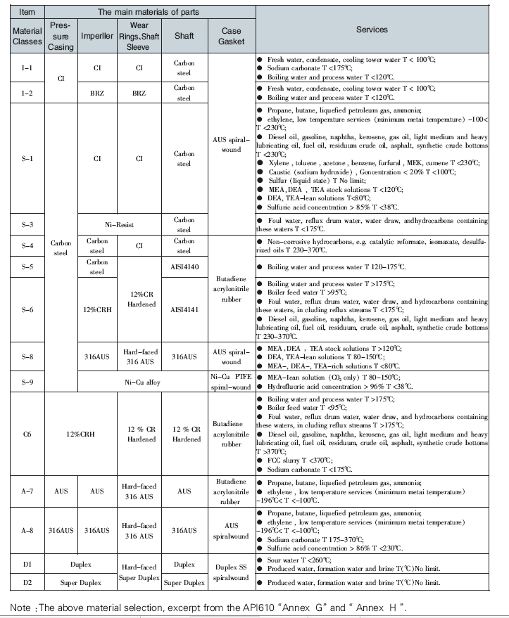
APS type petrochemical process centrifugal pump is to meet the requirement of modern construction of petrochemical plant. It is combined the technology with KSB and IR company and completely designed compliance with API610 standard. It is specialized in delivering crude oil, refined oil, and chemical raw material , intermediate product and end products with the advantage of high reliability, long service life and high performance.
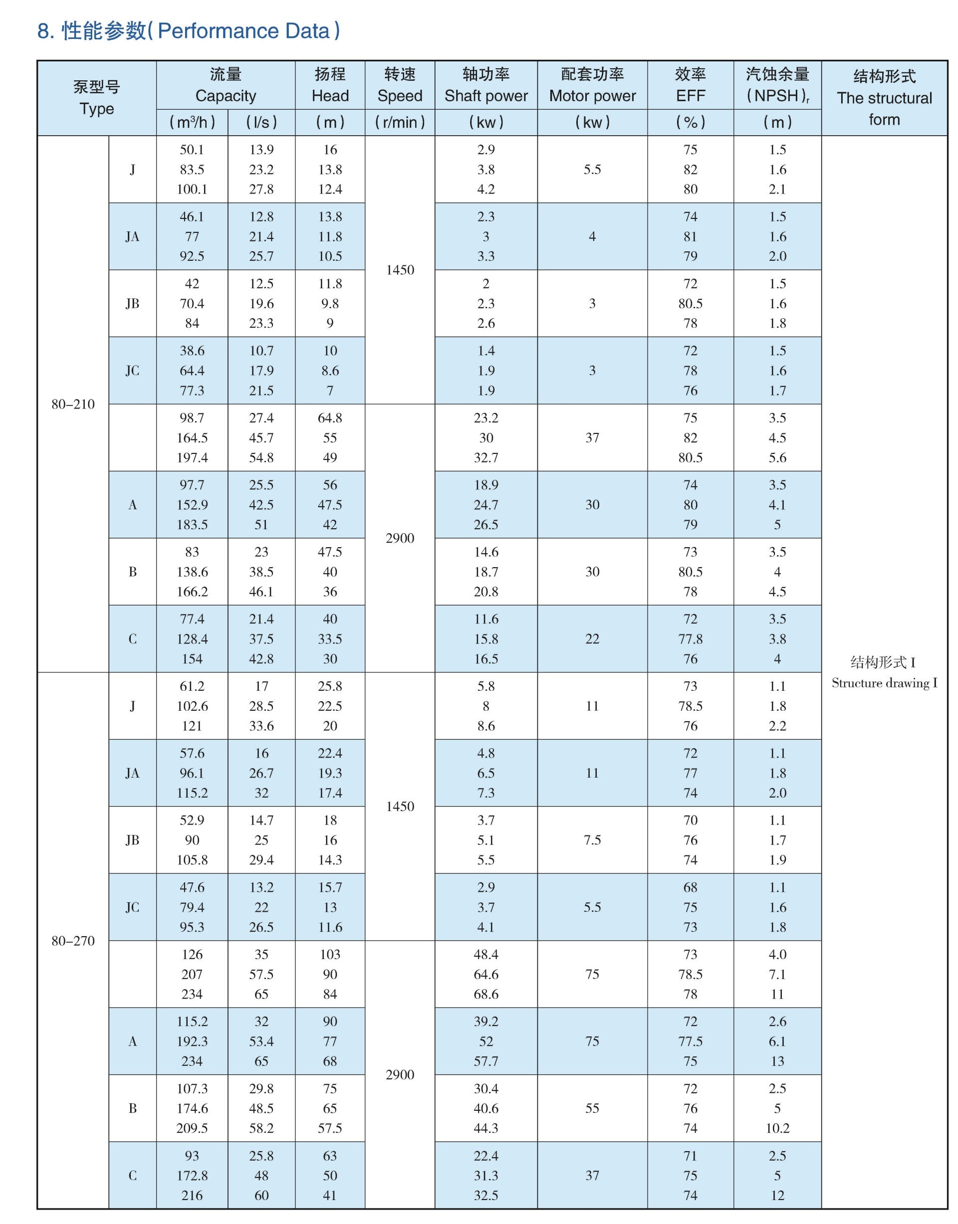
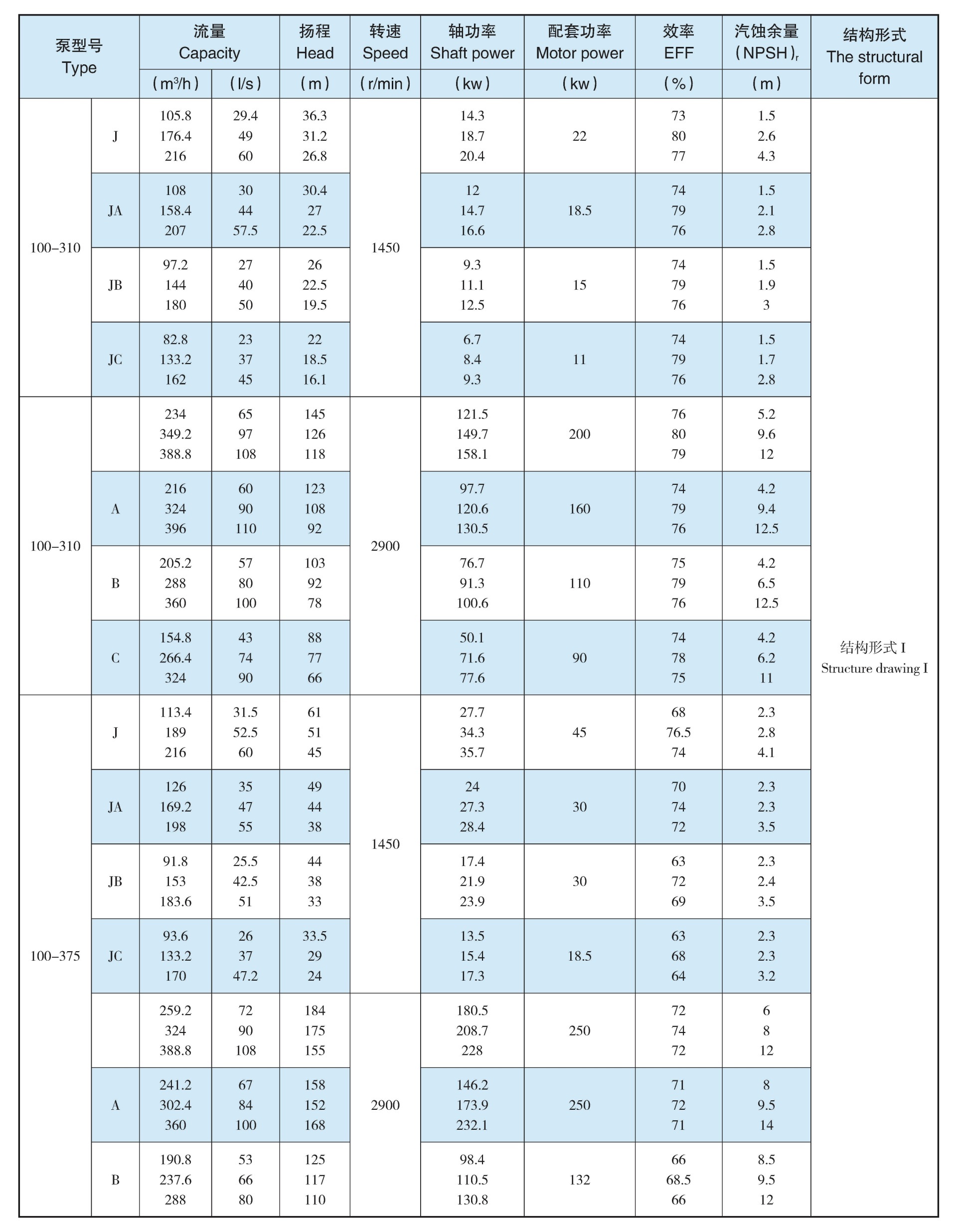
Main Performance Parameters
Outlet diameter DN:80-500MM
Capacity Q:20-7000 m³/h
Head H:7-300M
Work temperature T:-200℃-400℃
Solid parameter ≤80mg/L
Permissible pressure ≤5Mpa
Description of Pump Type
For example: APS 250-450A-J
APS: Petrochemical process centrifugal pump
250: pump outlet diameter (mm)
450: standard impeller diameter (mm)
A: Changed outer diameter of impeller (the max diameter without mark)
L: vertical mount
J: Pump speed changed (Maintain the speed without mark)
Pump Supporting program
Construction drawing
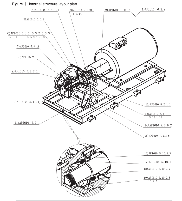

- Adopting flexible coupling to connect pump and electrical motor(See detail in API 610 6.2.2)
- Coupling and shaft is guarded by coupling guard. It is made of non-tapping and non-spark aluminum plate to ensure enough stiffness so as to bear static point loading of 900N(200lb) without any contact with moving parts (See detail in API 610 6.14)
- Pressure pump casing connected by six angle bolt(See detail in API 610 5.1.13), all the major joint of the pump casing use the double end studs(See detail in API 610 5.14)
- Tapping is adopted standard pipe size specification Rpl/2(see detail in API 610 5.1.1)for fittings between piping and pressure casing
- Impeller for solid wheel (see API610 6.4)
- It is more reasonable to adopt casing pressure designing(see detail in API 610 5.3.1)
- Sealing chamber with reasonable design(see API610 in figure 25 and table 6), the sealing gland and end of sealing chamber with excellent cooperation n(see API610 5.8.11)
- Cartridge seals are adopted. (see detail in API1682)
- Use the same pressure class flanges to connect inlet and outlet (see detail in API 5.4.2.1)
- Designing of bearing house is adopted structure with both oil lubrication and grease lubrication. It has a hole to discharge grease when adopting grease lubrication bearing house (see detail in API 65.11.4)
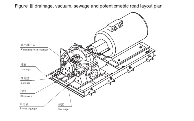
- Effusion box is installed in baseplate (see detail in API 610.6.3.1). Outline designing in line with API610 appendix D.
- Axially split face using composite is appropriate(see detail in API 610 8.2.1.1)
- Wear rings and running clearance is appropriate (see detail in API610 5.7), wear ring should have surface hardening treatment(see API610 5.12.1.12)
- Outlet flanges could bear certain pressure(see detail in API610 9.6.9.2)
- Screw hole block with steel cap or steel plug(see API610 7.4.3.6)
- Bearing to be fixed on the shaft through the interference fitting with shaft shoulder, ring and tongue-shaped lock washer nut.( see:API610 5.10.1.3)
- There are two radial bearing and one double-acting axial (thrust) bearing on each shaft. The double-acting axial bearing could compound with or without the two radial bearing(see detail in API610 5.10.1)
- Bearing box adopts the framework oil seal type effectively keeping the oil in the bearing box, and to prevent debris entering the bearing box(see API610 5.10.2.7)
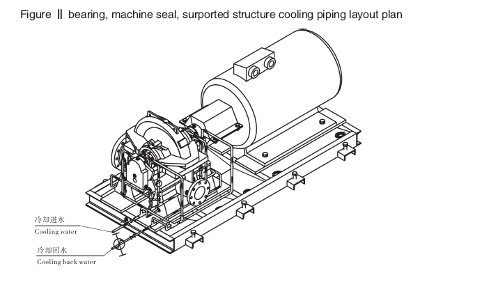
- Bearing lubricated by radiating type oil slinger (see API610 5.10.2.8). The water cooling the lubricating oil instead of cooling the bearing outer ring(see API610 5.10.2.5)
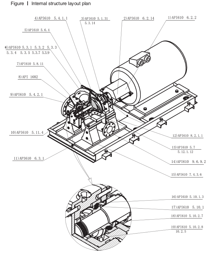
- Adopting flexible coupling to connect pump and electrical motor (See detail in API 610 6.2.2).
- Coupling and shaft is guarded by coupling guard. It is made of non-tapping and non-spark aluminum plate to ensure enough stiffness so as to bear static point loading of 900N (200lb) without any contact with moving parts (See detail in API 610 6.2.14)
- Pressure pump casing connected by six angle bolt (See API610 5.1.31) all the major joint of the pump casing use the double end studs.( See detail in API 610 5.3.14)
- Tapping is adopted standard pipe size specification Rpl/2( See detail in API 610 5.4.1.1)
- Impeller for solid wheel (see API610 5.6.4).
- It is more reasonable to adopt casing pressure designing
- Sealing chamber with reasonable design ( See detail in API 610 in Figure 25 and table 6), the sealing gland and end of sealing chamber with excellent cooperation n(see API610 5.8.11)
- Cartridge seals are adopted.(see detail in API 1682)
- Use the same pressure class flanges to connect inlet and outlet(see detail in API 610 5.4.2.1)
- Designing of bearing house is adopted structure with both oil lubrication and grease when adopting grease lubrication bearing house (see detail in API 610 5.11.4)
- Effusion box is installed in baseplate (see detail in API 610 6.3.1) Outline designing in line with API610 appendix D
- Axially split face using composite gasket seal (see API610 8.2.1.1).
- Wear rings and running clearance is appropriate (see API610 5.7):wear rings should have surface hardening treatment (see API610 5.1.12).
- Outlet flange could bear certain pressure (see detail in API610 9.6.9.2).
- Screw hole block with steel cap or steel plug (see detail in API610 7.4.3.6).
- Bearing to be fixed on the shaft through the interference fitting with shaft shoulder, ring and tongue-shaped lock washer nut. (see API610 5.10.1.3).
- There are two radial bearing and one double-acting axial bearing could compound with or without the two radial bearing (see API610 5.10.1).
- Bearing box adopts the framework oil seal type effectively keeping the oil in the bearing box, and to prevent debris entering the bearing box (see API610 5.10.2.7).
- Bearings lubricated by radiating type oil slinger (see API610 5.10.2.8). The water cooling the lubricating oil instead of cooling the bearing outer ring (see API610 5.10.28).
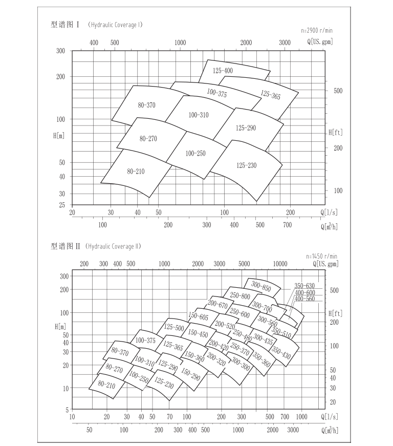
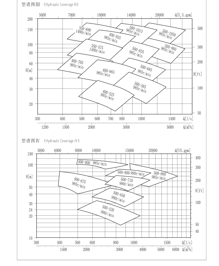
Hyraulic coverage
Advisory Message
To: Hunan M&W Pump Co., Ltd
Email: export@mwpump.com
Baoshui Road & Baishi Road, Jiuhua Industrial Zone,
Xiangtan Hunan P.R.C
Tel: +86-731-55599916
WhatsApp: +86 15116202855
Hunan M&W Pump Co., Ltd


