


XSR Hot Water Pump
Specifically engineered for thermal power plant municipal heat network, XSR can operate with or without external cooling water.
| Outlet diameter | 80 ~ 1600 mm |
| Capacity | 100 ~ 25,000 m³/h |
| Head | 10 ~ 240 m |
| Temperature | 0 ℃ ~ 200 ℃ |
| Working pressure | Up to 4 MPa |
XSR series single stage double suction split case pump are specially designed for transferring circulation water in heat network of thermal power plant. The pump for municipal heat network will drive the water flow like a circle in the network. Circulation water which flow back from the municipal heat network will be boosted by the pump and heated by the heater, and then transferred return to the municipal heat network.
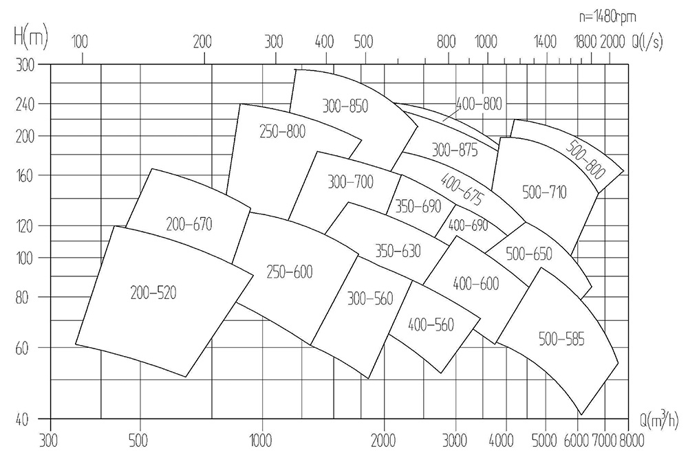
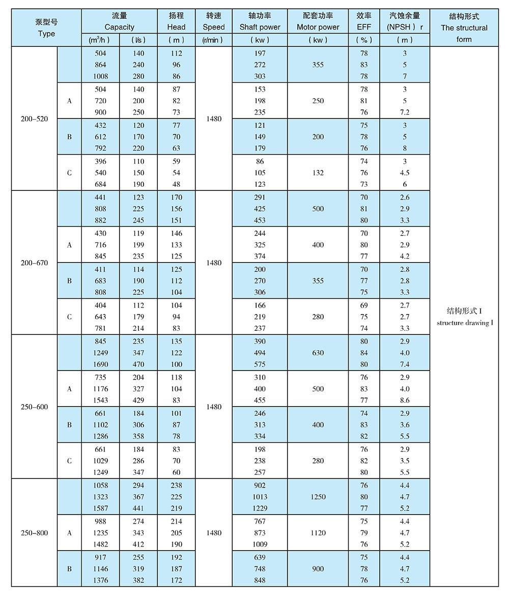
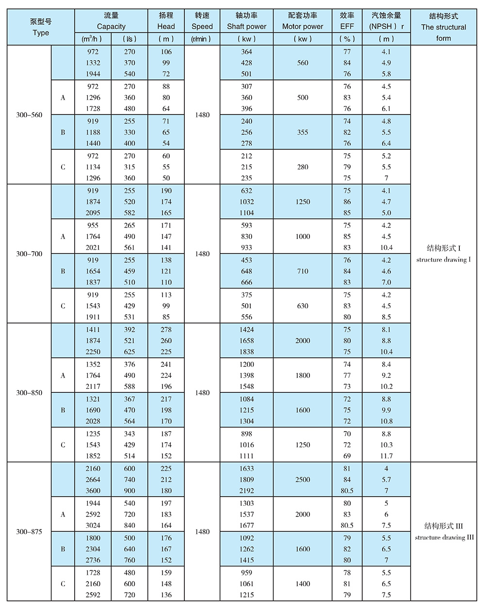
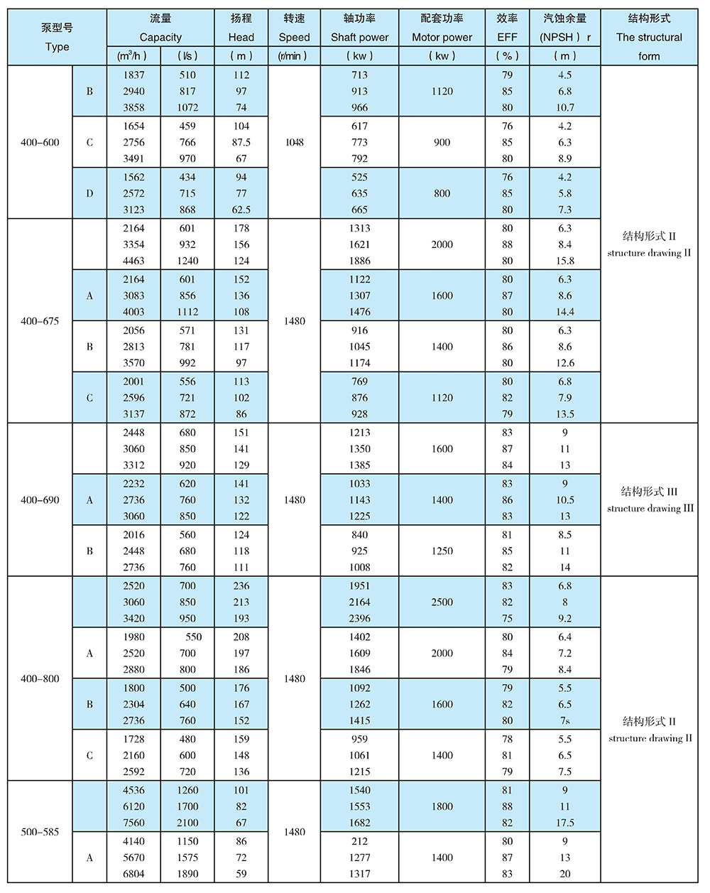
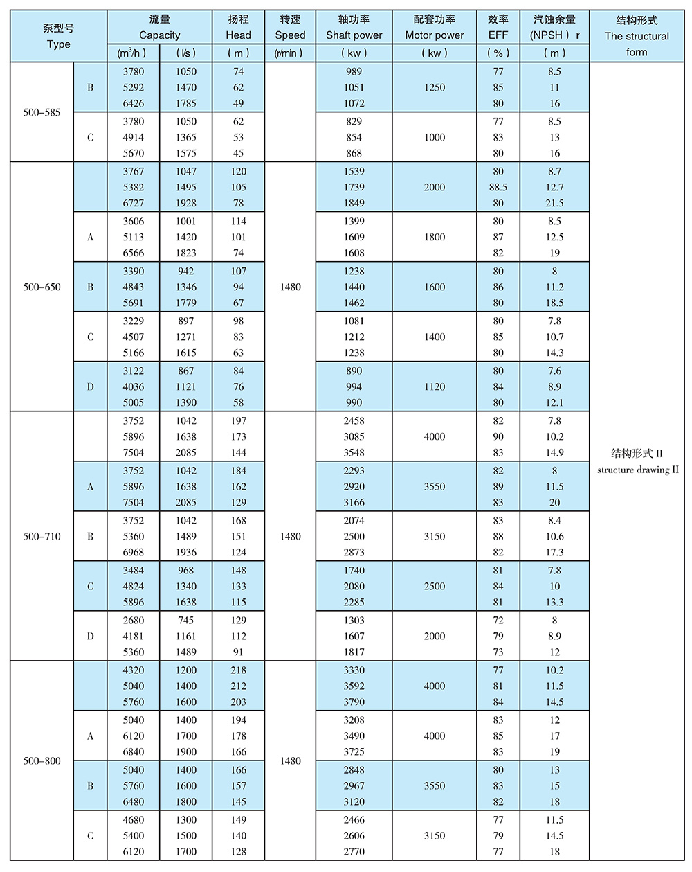
Main performance parameters
● Pump outlet diameter Dn: 200~900mm
● Capacity Q: 500-5000m3/h
● Head H: 60-220m
● Temperature T: 0℃~200℃
● Solid parameter ≤80mg/L
● Permissible pressure ≤4Mpa
Customized order available Circulating pump in heating network
Description of Pump Type
For example:XS R250-600AXSR:
250:pump outlet diameter
600:standard impeller diameter
A: Changed outer diameter of impeller (the max diameter without mark)
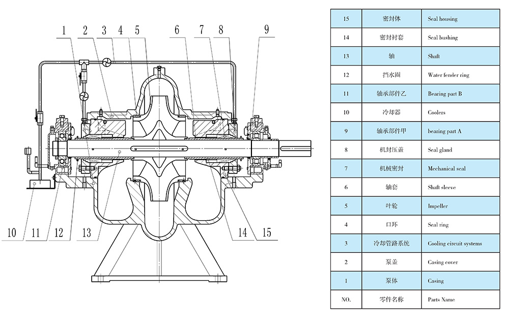
Recommended material list for main parts:
Casing: QT500-7,ZG230-450,ZG1Cr13, ZG06Cr19Ni10
Impeller: ZG230-450,ZG2Cr13, ZG06Cr19Ni10
Shaft: 40Cr、35CrMo、42CrMo
Shaft sleeve: 45、2Cr13、06Cr19Ni10
Wear ring:QT500-7 、ZG230-450 、 ZCuSn5Pb5Zn5
Bearing: SKF、NSK
1: Type XSR pumps work stably with less noise and vibration, due to short spacing between both side supports.
2: The same rotor of type XSR pumps can be operated in reverse direction to avoid damage to the pumps by water hammer.
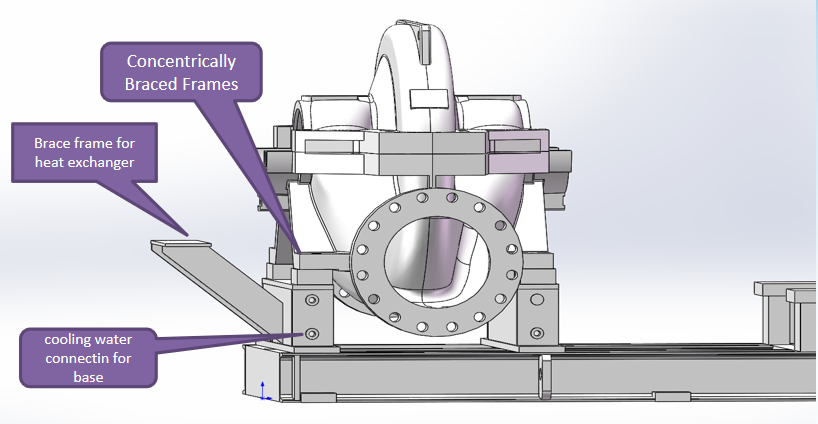
3):Unique design of high temperature form: outer cooling water will be available since the bearing with cooling chamber; the bearing could be lubricated by oil or grease,If the site has the same external ambient desalted water as the pumps transport medium ,and the pressure is 1—2 kg/cm2 higher than the pump inlet pressure, while mechanical seal washing water can be connected with above conditions are not available, please follow the following instruction: cooling and filtering the high temperature demineralized water which from the pump outlet to flush the mechanical seals, which could make the mechanical seals more stable and endurable; a water indicator should be fixed on the flush water system, which could monitor the flush water and adjust the water flow and pressure(usually the pressure should be 1-2kg/cm2 higher than the pump inlet pressure) ; Bimetal thermometer should be coupled behind the heater exchanger, and the alarming device optional, which could react while the temperature exceed limit; Also a differential pressure switch was optional, which would monitoring the heater exchanger. Above unique design makes the pump could work in high temperature conditions near 200 centigrade
4:Speed detection device coupled with speed measuring instrument and the probe will be configured at the shaft extension position if the pump was driven by variable frequency motor or steam turbine; othe1wise it will be configured at the coupling device if the pump was driven by normal motor with hydraulic coupling.
5: Type XSR pumps can be vertically or horizontally mounted according to different working condition, with High temperature packing seal or Mechanical seals; can also use cartridge seals, so it is very easy and simple to replace them.
6:With industrial design, the outline of XSR is clear and beautiful in line with modern aesthetics .
7:The efficiency of XSR pumps are 2%-3% higher than the same type pumps due to adopting advanced hydraulic model and thus reduce the operating costs significantly.
8:Choosing import brand bearing, and other parts material chosen by customer, make the pump suitable
for any operation condition and reduce the maintenance costings.
9: It is rapid and simple to assemble and dismount the rotor parts due to using elastic prestress assembling.
10:It is unnecessary to make adjustment to any clearance when assembling .
Email: export@mwpump.com
Baoshui Road & Baishi Road, Jiuhua Industrial Zone,
Xiangtan Hunan P.R.C
Tel: +86-731-55599916
WhatsApp: +86 15874130502
Hunan M&W Pump Co., Ltd


