Nanchang City Enhui Medical Hygienic Materials Co., Ltd.

  PRODUCTS

All categories

Related Products

There is currently no content to display
Please add data record on website background.

Relevant Information

There is currently no information to display
Please add data record on website background.
1/1
Number of views:
1000

Vertcal turbine pump

Retail price
0.0
Yuan
Market price
0.0
Yuan
Number of views:
1000
Product serial number
Quantity
-
+
Stock:
0
1
Product Description
Structure Feature
Technical Data
Precautions
Troubleshooting
Download

Type LC vertical long-shaft pump is the newly developed products with both domestic and overseas relevant manufacturer advantage after years of research. For delivering water, rain water, sewage and sea water with the temperature below 80℃. It is widely used in primary water plant, sewage treatment plant, metallurgical steel industry, power plants, mining, municipal engineering and irrigation and water conservancy engineering.


Description of Pump Type

● For example: 600LCB-60×3,600LCKX-60×3

● 600:Outlet diameter of pump is 600mm

● LC: Vertical long-shaft pump

● B: Non-pull-out rotator construction

● K: Pull-out rotator construction

● S: Outlet is above pump foundation

● X: Outlet is under pump foundation

● 60: (m)Head of designed point

● Stages of the pump(no indication when pump is single stage)

Main Performance Parameters

● Outlet diameter: 100~2600mm

● Capacity: 40~72000m3/h

● Head: 5~260m

● Solid parameter: ≤80mg/L

● Permissible pressure: ≤4Mpa


Pump Supporting Program and Services

We value the energy saving and environmental protection, by analyzing the requirements of media and operation environment, adopt optimal materials to make the pump operate safely, reliably, economically.

Construction Drawing

pull out rotor


We could not find any corresponding parameters, please add them to the properties table


LC vertical long shaft pump could be designed in single stage and multistage with inlet straight down, and outlet overhanging. There are two kinds of rotor parts: pull-out and non-pull-out. The axial force can be born by either motor or pump itself. Teflon, rubber and thordon are common material which used for guide bearings and other material could be adopted to meet the uses’ requirements. Protection sleeve are on the shaft and clean pressure water through it in order to lubricate and cool guide bearing.


1.Type LC has adopted advanced hydraulic model same as Ingersoll Rand, Hitachi and Kubota which with high efficiency. Compared with similar product in domestic, LC type has higher efficiency 3% to 5% and requires lower motor power. Therefore, it is not only reduce the purchasing cost, but also reduce use cost by achieving the purpose of energy saving and reducing consumption.

2.Pump outlet diameter which smaller than 1000 mm has systematization, standardization. Spare parts will be produced in advance according to user’s profile and could be supplied timely when order placed.

3.With vertical installation, the pump occupies less space and saving the cost of building pump house and civil engineering. No need of pump house if the pump installed outdoor with outdoor motor.

4.Weight of rotor is in vertical direction with the advantages of small radial force, smooth operation, small vibration, low noise and long service time.

5.Pull-out rotor type with the advantages of easy maintenance.

6.No need of filling water because impeller is submerged in the fluid.

7.Pump shaft, intermediate column and shaft sleeve pipe are multi-section. Adopted sleeve coupling on the shaft leads radial coaxial high and can maximum reduce vibration of the pump unit. Quantity of intermediate column could meet the requirements of different submersible depth.

8.Impeller and diffusor can be designed in multistage to apply to different pump head.

9.The length of drive shaft is reasonable and has enough rigidity. The critical speed of drive shaft is more than triple of that of pump. Pump unit will never resonance.

10.Pump intermediate column is connected by flange, there is a guide bearing support. Teflon, rubber and thordon are used for guide bearings. Shaft protected by guard column. No need of guard column when pump delivering clean water and cooling and lubricating water for guide bearing. Guide bearing should be supplied with exterior cooling lubricating water, while delivering sewage. It could add special structure where the operating site does not have clean water or the clean water cost is high. It makes cooling lubrication to guiding bearings when the fluid is filtered and precipitate. The lubrication water system could add some control elements of capacity, pressure relay and so on. Pump will not operating if the water output less than rated water output. Replay will issue a warning signal circuit—red light alert and buzzer alarming in the control room when the pump lack of water or pressure (maybe caused by a blocked pipe). The problem could be solved by opening the systematic valve to supply the water and troubleshoot the failures. This control system could achieve remote supervision and control.

11.Axial force of pump and weight of rotor parts are borne by thrust bearing on either motor or pump. Thrust bearing with thin oil lubrication, and external water cooling and can be embedded temperature control element.

12.The pump shaft seal with intercepting disc structure of the packing seal. Leakage will go into into the pump pit or trench which keep pump room clean and tidy. There is replaceable shaft sleeve in shaft seal and guide bearing to protect shaft and it is convenient to adjust axial location of impeller by nut in bearing parts upper end or pump coupling.

13.Pump can be equipped with controller which can automatically start and stop pump according to liquid level, give an alarm for over loading which can achieve remote computer control of many pumps.


1. Inspection before starting

Be sure to check the followings:

(1) Insure pump plate fixed on foundation;

(2) Insure coupling and pump unit alignment;

(3) Insure piping connected by requirements;

(4) Insure motor installed by Installation and operation instruction;

(5) Insure the rotor of pump rotate easily (at least a circle);

(6) Insure the coupling guard installed;

(7) Insure the operator fully understand the safety specification that they should obey and the failures may be occurred;

(8) Insure the shaft seal liquid or cooling liquid lead-in by requirements;

(9) Insure the shaft seal installed by operation instruction;

(10) Insure the auxiliary device installed by operation instruction (If they exist);

(11) nsure the bearing have lubricated well, especially insure new pump grease or thin oil do not reduce or go bad;

(12) Insure the air trapped in pump escaped。


2. Shaft Seal

Open valves properly for stuffing box seal


3. Air exhaust

Pump and piping should fill of medium before starting, there are two methods: creation of vacuum or priming. If the pump operated on the suction state, exit gas by bolt hole on top of the pump casing.

Note: When creation of vacuum, evacuate air by bolt hole on top of the pump casing. When priming, open both side low pressure volute chamber of pump casing and the top plug, to get rid of pump vibration by remained air in pump.


4. Starting

(1) Close outlet valve;

(2) Open inlet valve completely;

(3) Open all auxiliary piping (cooling, heating, sealing, rinsing and lubricant liquid), and check all capacity and pressure;

(4) Starting pump after finishing above procedures;

(5) When the system starting deliver medium and the pressure reading at pressure gauge rise up, open outlet valve slowly。

Note: Forbid pump operating without liquid! Only close outlet valve when the pump start and shutdown, otherwise will damage the pump by overheating.


5. Operation

(1)

Confirm operating point


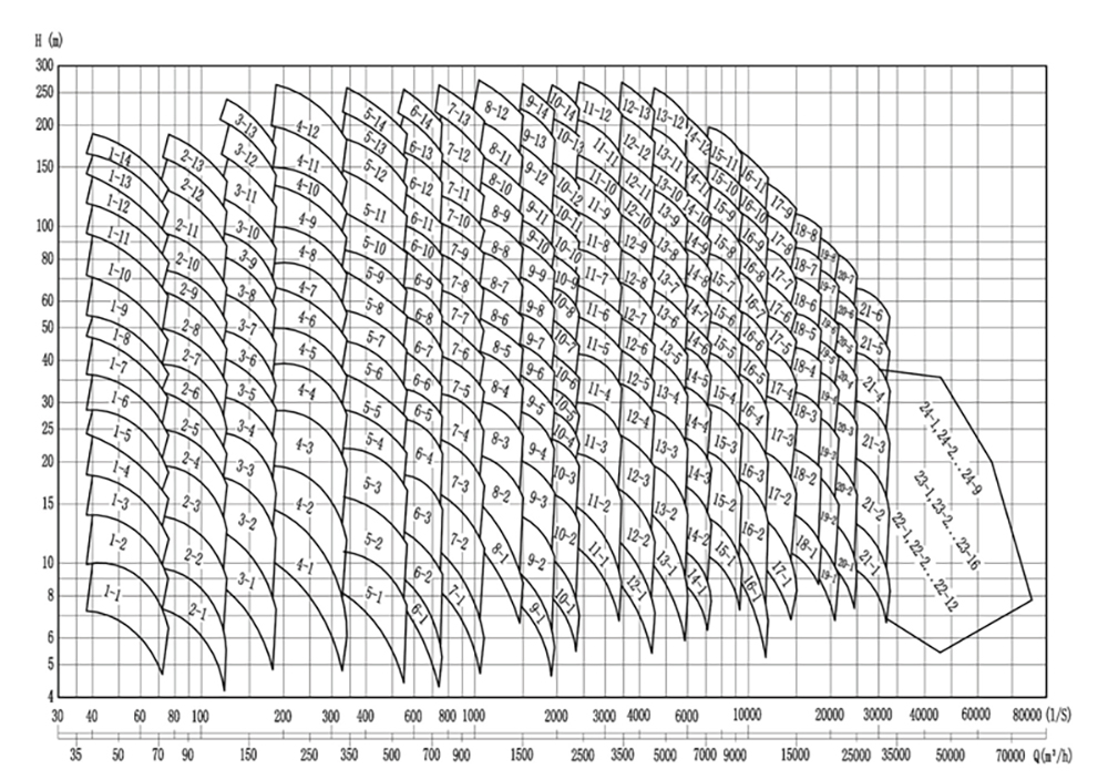
According to Q-H performance curve of pump, capacity Q varies with the actual operation head. The head depended on the system head (including the altitude difference between inlet and outlet, piping, valves, radiator and so on). So the pump actually operating point B depends on pump performance

curve Q-H and system performance curve Q-HA.

Once capacity settled, the shaft power, efficiency, NPSH settled as well. Pump has limited working range. The minimum capacity are shown as Qmin in Q-H performance curve. Maximum capacity are depended on the cross point of pump tolerance NPSH and system valid NPSHA. Adjust valve can change performance curve Q-HA of system, thereby adjust operation performance, makes pump operation stable and high efficiency.

(2) Operation management

Should pay attention to followings:

a. Pump should work stably

b. Forbid pump operating without liquid

c. To prevent medium temperature rise up, pump can not be run long period when close outlet valve

d. Generally, the bearing temperature not higher than 35℃ of ambient temperature, absolute

operation temperature less than 100℃.

e. Check oil level regularly if use thin oil. Deep groove ball bearing of grease lubrication no need routine maintenance.

f. Do not close inlet valve (if it is exist) when pump operating.

g. Periodical inspection and start jury pump.

h. Check auxiliary piping whether connected well.

i. Check elastic element of coupling, if worn replace immediately.

j. For stuffing box seal there should have a slight drip when running, push stuffing box gland gently until there is a slight drip (about 15-30 drop/min ).

For mechanical seal the seal leakage should reduce gradually. It is about 0-5drop/min after

starting few hours. If the seal leakage increase gradually and reach about 30-60drop/min, should check or adjust mechanical seal.


6. Shutdown

Close discharge valve.

Insure the pump unit stop smoothly when shutdown the motor. Pump should have a proper after-running period, cut heat source at this time, so that the delivered medium can cool down completely and avoid of producing any heat inside pump.

Close suction valve if pump stop work for a long period of time.

Close auxiliary piping, the shaft seal should use seal lubricant even though at stopped state. Evacuate all medium in pump and piping when freeze or stop work for a long-term, so as not to frost crack.


7. Storage

Every pump has inspected strictly before delivery. Recommend to adopt following procedures to store pump.

(1) Store new pump

If store pump at indoor, clean dry place and follow the storage requirements, the longest storage time is 12 months.

(2) If equipment is to be stored for long periods of time should follow below procedures.

a. Pump should keep in installation state and inspect work condition regularly. Start pump once every month or every three months (about 5 minutes). Check running condition before starting pump to insure there is enough liquid.

b. Dismantled pump from piping and check it according to section 5.1 to 5.4. Apply protective agent on inside pump casing especially the gap of the impeller, apply on suction and discharge, then cover the suction.

c. Operation after storage

Inspect and maintain completely before starting pump, especially shaft seal and bearing lubricant. Reinstall all safety protection devices according to requirement before starting.

Problem

Causes

Remedy

starting load too high

1. Starting without closing discharge valve;
2. packing too tight lead to lubricant water can not flow into;
3. Misguide by failing of overcurrent protector

1. Close the valve;
2. Loose packing or check the valve of water seal, check if packing ring against the nozzle of lubricant water,
3. Adjust current limiting threshold or repair overcurrent protector.

Packing overheating

1.Packing  too tight;
2.Cooling water can not flow into packing box;
3. Damage in the surface of shaft or shaft sleeve;

1. Loose packing properly;
2.Loose packing or check if the water seal pipe clogged;
3.Repair shaft or shaft sleeve;

Packing leakage excessive

1. Packing worn;
2. Packing too loose;
3. Shaft curved or vibration;
4. Wrong packing bind;
5. Unclean seal water wore shaft;
6. Shaft sleeve worn;
7. Wrong packing;
8.The pressure of seal chamber too high or too low;

1. Replace packing;
2. Tighten packing box gland or add more packing;
3.Align or replace shaft;
4. Rebind packing;
5.Filtrate or use exterior source as seal water, repair;
6.Replace shaft sleeve;
7.Replace packing;
8. Adjust the pressure and capacity of seal liquid or use a sealing liquid from an external source.

Mechanical seal leakage

1. The nominal pressure of mechanical seal lower than actual work pressure;
2.Unreasonable reduction of Mechanical seal mounting,friction components not contact effective;
3. The rust of shaft sleeve surface cause rotating seal ring of mechanical seal sealing failure;
4. The delivered medium physical and chemical property causes O-ring loss elasticity;
5. The delivered medium physical and chemical property causes spring mechanical seal of loss elasticity;
 6. Impurity enter friction components and damaged their surface;
7. The liquid of friction components volatilize that cause their surface burning-out;

1. Change the type of mechanical seal;
2. Reinstall;
3. Clean shaft sleeve or change their material;
4. Change material;
5. Replace or change material;
6. Filtrate or use exterior source as rinsing water;
7. Adjust rinsing medium or measure;

Bearings over heating

1.Improper centering;
2.Improper adjustment or resonance in piping;
3.Overlarge .axial force;
4.Unbalance rotor ;
5. The rigidity of foundation not enough;
6. Incorrect bearing installation or improper clearance;
7. Wore or loosened shaft;
8. Improper lubrication;
9. Oil splash ring can not get oil;
10. Poor circulation in pressure lube;

1. Readjust;
2.Readjust;reduce piping if necessary; use vibration-absorptive material;check and repair;
3. Check and adjust special working point;check capacity and running state;
4. Rebalance;
5.Strengthen the rigidity of foundation;
6. Check and choose bearing with properclearance;
7. Check and replace bearing;
8. Check the amount of oil first, too much or so little will affect operation, then check the quality of oil, especially applicable temperature;
9.Check and eliminate, the causes of can not get oil may related with oil quality, speed,wore of oil splash ring and oil circulation;
10. Check the system of pressure lube;

Vibration and noisy

1. Special working point B is not design point;not design point; low or high will cause vibration and noisy;
2. Insecure foundation;
3.Loosened anchor bolt;
4.Insecure piping supports;
5.Piping resonance;
6.Cavitations;
7. Air cell in medium or piping leakage;
8.clogged inlet or outlet of impeller;
9. Improper centering;
10. Unbalanced pump rotor or motor rotor;
11.Worn coupling pin or unhealthy coupling connection;
12. Worn bearing;
13. Shaft curved;
14. Friction in rotating elements;
15.Loosened or broken rotating elements;

1. Adjust system special working point or pump design parameters;
2. Strengthen foundation;
3. Tighten anchor bolt;
4. Strengthen piping supports;
5. Expanding the distance between pump discharge and elbow, use vibration-absorptive material in piping connection, adjust piping arrangements;
6. Rise water level, reduce suction line loss, increase suction pressure by using inlet throttle valve;improve pump cavitations performance;
7. Check and eliminate, add discharge valve;
8. Clean impeller, clean impurity of pump and piping, check strainer and suction nozzle;
9. Recentering;
10.Rebalance;
11. Replace pin, rotate coupling 180°, eliminate error of pin  hole, adjust the unit to insure there is a necessary clearance in coupling;
12. Repair or replace bearing;
13. Align or replace shaft;
14. Eliminate friction;
15. Eliminate, replace worn parts;

water attack

Air in pump or piping

Evacuate air and eliminate the causes

Pump starts pumping then stops

1. Clogged in suction line or impeller;
2.  Air  cell in piping;
3. Lift too high  valid NPSH too low;
4. Air enter shaft seal;
5. Water level decrease too much;

1. Clean impeller, clean impurity of strainer and suction piping;
2. Improve suction line, adjust piping arrangements, add discharge valve;
3. Increase entrance pressure, increase suction pressure by using inlet throttle valve; low the height of pump installation; change suction line if too much line loss;
4. Check pressure and amount of seal liquid if they are suitable operating requirements, replace packing or other shaft seal, check the mounting position of water seal ring;
5. Rise the lowest water level, increase entrance pressure, increase   suction   pressure by using   inlet   throttle   valve;


Previous
Next

Download

Previous page
1
这是描述信息
这是描述信息
这是描述信息

Add: Jiuhua Industiral Park,Xiangtan City,Hunan Province,China

这是描述信息

Call us:+86-0731-55599916
            +86-18673110460


Hunan M&W Pump Co., Ltd   湘ICP备14003804号-2     www.300.cn      Manager

搜索
Search