


1/1
Number of views:
1000
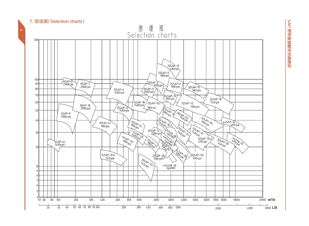
SAP split case pump
● Pump outlet diameter Dn: 100~900mm
● Capacity Q: 72~20000m3/h
● Head H: 7~186m
● Temperature T: 0℃~80℃
● Solid parameter ≤80mg/L
● Permissible pressure ≤5Mpa
Retail price
0.0
Yuan
Market price
0.0
Yuan
Number of views:
1000
Product serial number
Quantity
-
+
Stock:
0
Product Description
Structure Feature
Technical Data
Precautions
Troubleshooting
Download
SAP pump is a single-stage double-suction split case centrifugal pump. It is a new product developing from SA-pump on the basis of structural optimal design. The products reserve the characteristics of SA type pump of good hydraulic performance, high efficiency, as well as made a new improvement in structure comprehending the technology of West German KSB company and double-suction pump of United States IR company, make it more reasonable and reliable.
This group transfer branch water containing solid particle and liquid physics chemical properties similar to water, transferred media temperature are 0℃~80℃, suitable factory, urban, mining, power generation, water resources engineering, drainage or water supply pump.
Main performance parameters
Pump outlet diameter Dn:100~900mm
Capacity Q:72~20000m3/h
Head H:7~186m
Temperature T:0~80℃
Pump Supporting program
|
Item |
Pump Supporting Program A |
Pump Supporting Program B |
Pump Supporting Program C |
|
|
1 |
2 |
|||
|
Pump casing |
Grey cast iron |
Ductile cast iron |
Ductile cast iron |
Extra low carbon stainless steel |
|
Impeller |
Grey casting iron |
Cast steel |
Stainless steel |
Duplex S.S |
|
Shaft |
#45 steel |
#45 steel |
Stainless steel |
Duplex S.S |
|
Shaft sleeve |
#45 steel |
#45 steel |
Stainless steel |
Extra low carbon stainless steel |
|
Wear ring |
Grey casting iron |
Cast steel |
Cast steel |
Duplex S.S |
|
Services |
For pure water and lower Strength applications |
For pure water high strength applications |
For media with more solid impurities,PH<6 Chemical corrosion and for high strength applications |
|
|
These configurations are recommended by the manufacturer,customers could change materials according to specific needs. |
||||
Description of Pump Type
For example:10SAP-6A- L-M(F、Y)-J
10 —— Suction diameter divided by 25
(the suction diameter is 250 mm)
SAP —— Single stage double suction, split case centrifugal pump
6 ——Integer after the specific speed is divisible by 10
A —— Changed outer diameter of impeller
(the max diameter without mark)
L —— Vertical type
M —— Anti-frication
F —— Anti-corrosion
Y —— Anti-oil
J —— Pump speed changed
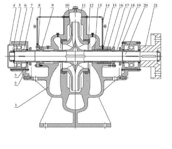
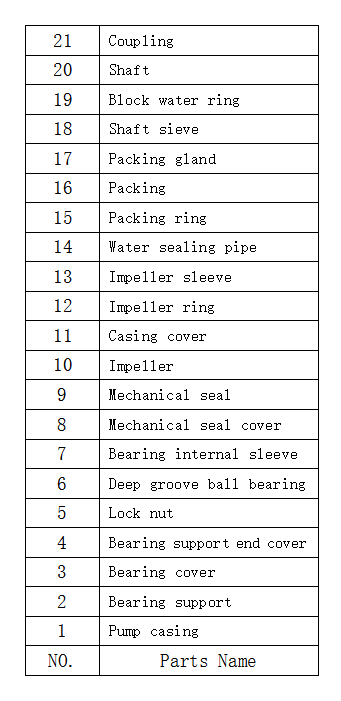
Construction drawing I
 |
 |
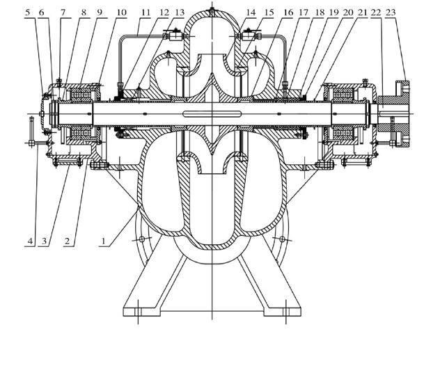
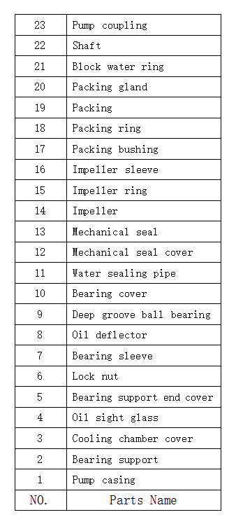
Construction drawing II
 |
 |


Add: Jiuhua Industiral Park,Xiangtan City,Hunan Province,China

Call us:+86-0731-55599916
+86-18673110460

Email:export@mwpump.com
Hunan M&W Pump Co., Ltd 湘ICP备14003804号-2 www.300.cn Manager
搜索